ROS Gazebo / computer vision / controls
Autonomous Lane Detection Vehicle
A simulated autonomous vehicle uses a ROS Python controller, OpenCV lane detection, projective geometry, and PID steering to navigate a yellow-lined Gazebo track from live camera feedback.
What this proves
Vision-derived steering without predefined waypoints.
The project replaces waypoint-following with sensor feedback. A
simulated Kinect/depth camera publishes 640x480 color frames in ROS
Gazebo; the controller detects lane lines, estimates a vanishing-point
steering error, and publishes cmd_vel corrections through a PID loop.
- Simulation
- ROS Gazebo simulation-in-the-loop vehicle with camera sensor feedback
- Perception
- HSV yellow isolation, Canny edge detection, ROI crop, HoughLinesP
- Geometry
- Vanishing point from two lane-line intersections mapped into steering angle
- Control
- ROS Python PID controller publishing Twist commands to adjust bearing
Video evidence
Track traversal and lane-detection views.
Alternative Track Demonstration
Camera Perspective
Lane Detection Overlay
Code-level pipeline
From image frame to steering command.
ROS Sensor Input
Subscribed to `/camera/color/image_raw` and converted frames from ROS `Image` messages into OpenCV BGR images using `CvBridge`.
Color-Space Filtering
Converted BGR to HSV, masked a tuned yellow range, and isolated lane pixels before edge detection to avoid horizon-line interference.
Canny and Hough Lines
Applied Canny thresholds of 20/65, cropped a triangular ROI, and used
cv2.HoughLinesP to extract candidate lane segments.
Vanishing-Point Error
Fit left/right lane lines, solved the two-line intersection, shifted the image origin to bottom-center, and converted the result to an angular steering error.
PID Steering
Used `Kp=.5`, `Kd=.25`, `Ki=0`, saturated angular velocity to the motor bounds, and published `Twist` messages with linear velocity 1.2.
Engineering Limits
Documented static gains/thresholds, frame-rate sensitivity, yellow object ambiguity, thin-lane failures, and difficulty with sharp turns.
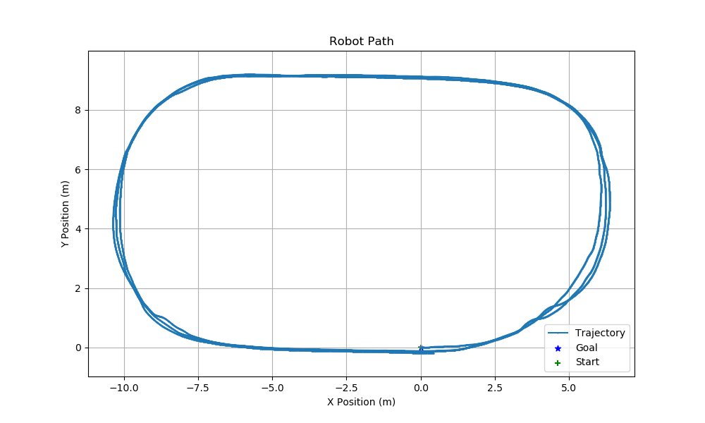
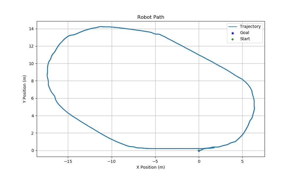
Results
The vehicle completed repeated track loops.
The project report includes path plots from the main and alternative tracks, along with a written analysis of where the controller succeeds and where the current lane-detection/PID assumptions break down.
Future iteration
A useful base for validation work too.
- Add a test harness with procedural track shapes and expected steering behavior.
- Parameter-sweep Canny, Hough, and PID gains across track widths and turn radii.
- Introduce recovery behaviors for one-line/no-line detection states.
- Compare static thresholds against adaptive color/edge detection under lighting changes.
- Record metrics for lap completion, lane departures, control saturation, and frame latency.